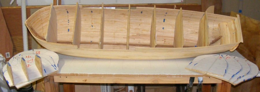
 12/20/2011: With everything set up, it was time to pull out some forms. I started with the aft-most one with the transom forms attached. It took a little tapping
with the upholstery hammer to get it loose down in the deadwood, but it came out without any damage to anything. I intended to only pull out every-other form,
but the hull was holding it's shape so well, and I was enjoying it so much, I eventually left only 4 forms in. I had to keep some in to stand the hull
up inverted to work on the bottom. With 11 forms pulled out the hull lost about 10-12 pounds, making it a lot easier to handle.
12/20/2011: With everything set up, it was time to pull out some forms. I started with the aft-most one with the transom forms attached. It took a little tapping
with the upholstery hammer to get it loose down in the deadwood, but it came out without any damage to anything. I intended to only pull out every-other form,
but the hull was holding it's shape so well, and I was enjoying it so much, I eventually left only 4 forms in. I had to keep some in to stand the hull
up inverted to work on the bottom. With 11 forms pulled out the hull lost about 10-12 pounds, making it a lot easier to handle.
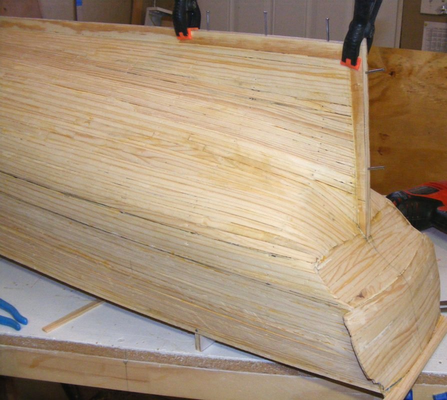
12/22: I made a quick stand, then attached the sternpost and the forth and aft-most section of the keel as well as the rest of the stem.
The nails just hold the alignment and are pulled after the glue sets.
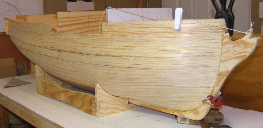
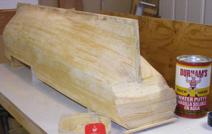
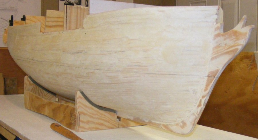
12/23: Puttied up the hull with Water Putty. As it set, the transom top was trimmed to shape and an internal brace installed to hold the transoms curve.
After some sanding I marked the waterline, just for the heck of it. I also added a little padding the stand. The hull will get another application of putty and then it's more sanding.
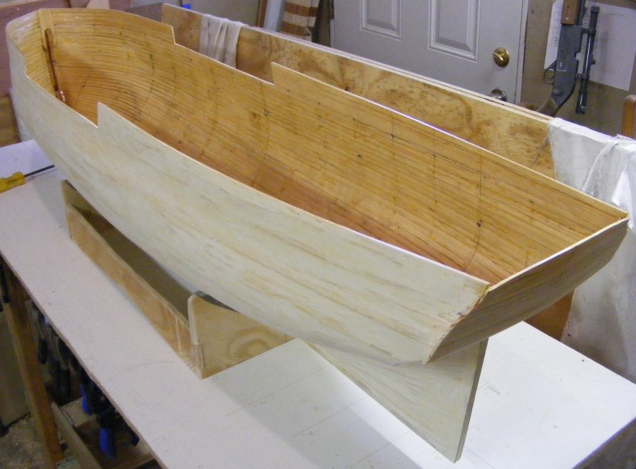 12/25: Went out to the shop and found that Santa Claus had not resined inside the hull as I had asked in my letter. I think I'm going to cancel my subscription,
I mean it's not like I asked him to glass the outside. Anyway, I pulled out all the forms and got a coat of resin painted into the hull.
12/25: Went out to the shop and found that Santa Claus had not resined inside the hull as I had asked in my letter. I think I'm going to cancel my subscription,
I mean it's not like I asked him to glass the outside. Anyway, I pulled out all the forms and got a coat of resin painted into the hull.
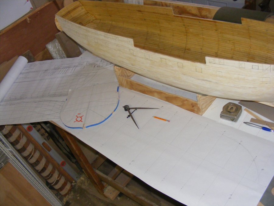
12/26: I decided to use a paper template to layout the gunports, moldings, etc, on the hull and I printed out the same drawing I was working from in section on 8-1/2" x 11" paper
on my laser printer instead of wasting paper printing it on the plotter.
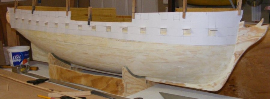 Unfortunately, the same image at the same 100% came out smaller on the laser than it did on the plotter. I tried playing with scaling, but couldn't get a good match,
so I took some scrap paper from the plotter and traced what I wanted from the working drawing hanging on the shop wall. While I could trace most of it, items up forward
in the rounding of the bow couldn't be traced from the flat profile, but had to be projected onto the plan view to get their proper position on the hull.
All these details were marked on the hull and will be visible through the fiberglass, once applied.
Unfortunately, the same image at the same 100% came out smaller on the laser than it did on the plotter. I tried playing with scaling, but couldn't get a good match,
so I took some scrap paper from the plotter and traced what I wanted from the working drawing hanging on the shop wall. While I could trace most of it, items up forward
in the rounding of the bow couldn't be traced from the flat profile, but had to be projected onto the plan view to get their proper position on the hull.
All these details were marked on the hull and will be visible through the fiberglass, once applied.
 12/27: In preparation for installing internal framing and structures, I began drawing out a plan view with dimensions for the spar deck and gun deck beams taken directly from the
building forms and profile view. I determined the deck height from the profile, and it's width from the forms and marked that data on what will become a new plan view of the
spar deck and gun deck.
12/27: In preparation for installing internal framing and structures, I began drawing out a plan view with dimensions for the spar deck and gun deck beams taken directly from the
building forms and profile view. I determined the deck height from the profile, and it's width from the forms and marked that data on what will become a new plan view of the
spar deck and gun deck.
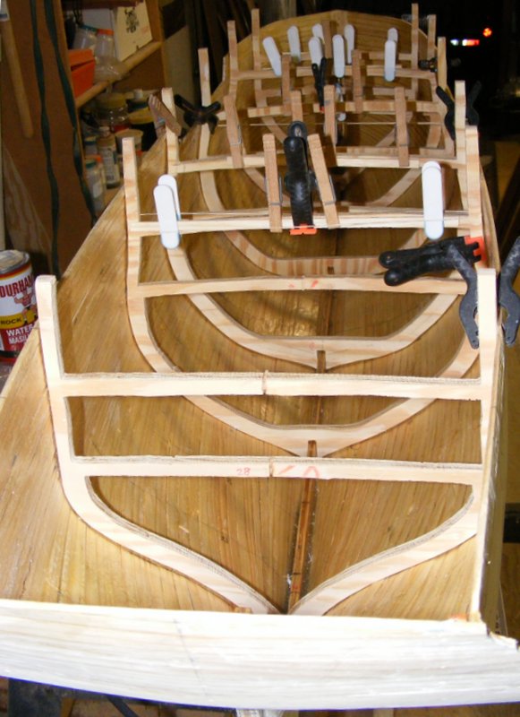 1/6/2012: I chose 6 forms to cut out and reinstall as frames. Basically, every other form. This will better help hold the hull's shape, provide support for the equipment deck
that the RC running gear will be installed on, and include some gun deck and spar deck beams. False frames will be installed between these, framing hull openings,
but will only run from the gun deck up to the rail. There will be ceiling planking inside from the gun deck up so the hull will be it's scale thickness above the gun deck.
1/6/2012: I chose 6 forms to cut out and reinstall as frames. Basically, every other form. This will better help hold the hull's shape, provide support for the equipment deck
that the RC running gear will be installed on, and include some gun deck and spar deck beams. False frames will be installed between these, framing hull openings,
but will only run from the gun deck up to the rail. There will be ceiling planking inside from the gun deck up so the hull will be it's scale thickness above the gun deck.
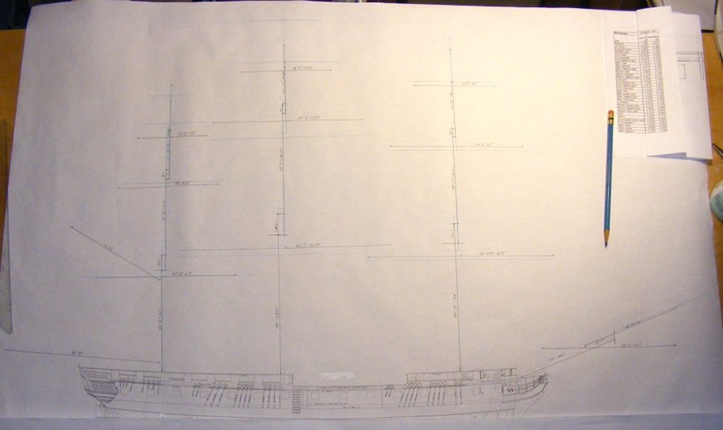 1/7: I laid up a spar plan in 1:96 scale using the standard 38 gun frigate dimensions from Gardiner's Frigates of the Napoleonic Wars. Over it, in blue pencil I also
laid in Macedonian's spar dimensions as taken off in 1818 according to Chapelle's History of the American Sailing Navy. Looking at the numbers it looks like
the American dimentions are longer, but in the masts, a lot of that is taken up in the doublings. The American rig is only a little larger than the British standard.
The American topsails ride slightly lower, and the cross jack is significantly longer.
1/7: I laid up a spar plan in 1:96 scale using the standard 38 gun frigate dimensions from Gardiner's Frigates of the Napoleonic Wars. Over it, in blue pencil I also
laid in Macedonian's spar dimensions as taken off in 1818 according to Chapelle's History of the American Sailing Navy. Looking at the numbers it looks like
the American dimentions are longer, but in the masts, a lot of that is taken up in the doublings. The American rig is only a little larger than the British standard.
The American topsails ride slightly lower, and the cross jack is significantly longer.
So, now I'm wondering if the 1818 table is an Americanized rig done to Macedonian's existing extra sails and spare spars from when she was repaired at sea
by Decatur. To get some idea of that, I plan to overlay the spar plan of the US frigate Chesapeake; a vessel of comparitive size to the Macedonian and see
if there's a significant difference in a purely American rig.
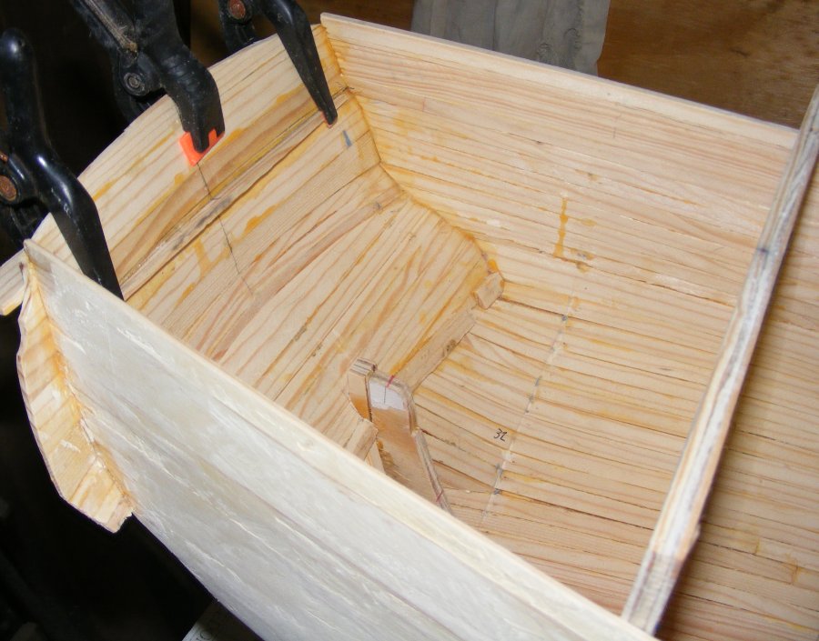
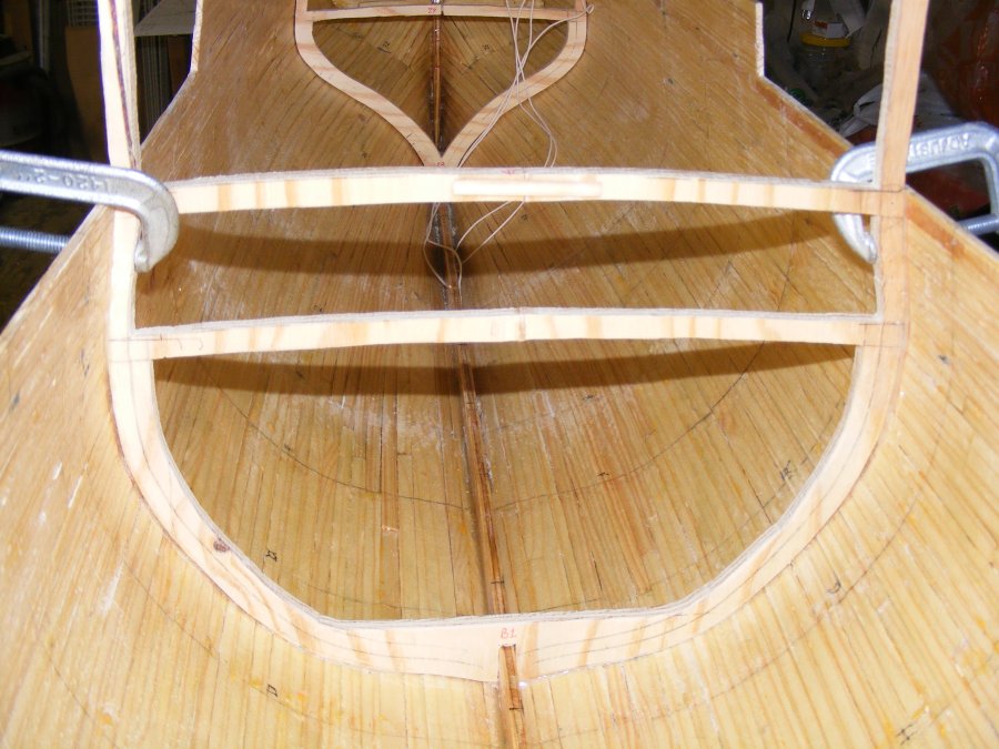 1/8: The first frame was epoxied into the hull. This one is between stations B & C on the plan, so I designated it B1. It was glued in with 5 minute epoxy made into a paste
with very fine sawdust from the bench sander. This one will get cut up a bit when the main hatches are framed in through it. In the picture you can see where the inside
of the hull was sanded where the other frames will go in, and everything above the gun deck line, where the gunport framing and false frames will go in.
1/8: The first frame was epoxied into the hull. This one is between stations B & C on the plan, so I designated it B1. It was glued in with 5 minute epoxy made into a paste
with very fine sawdust from the bench sander. This one will get cut up a bit when the main hatches are framed in through it. In the picture you can see where the inside
of the hull was sanded where the other frames will go in, and everything above the gun deck line, where the gunport framing and false frames will go in.
 1/10: With all the frames epoxied in place I noticed that something wasn't quite right and investigating I found that the focs'l deck beams in the forward two frames were
drawn and cut too high on the port side. No big deal, I just cut them and reglued them in the right place - thinking the whole time; "measure twice - cut once."
Now to just follow that addage.
1/10: With all the frames epoxied in place I noticed that something wasn't quite right and investigating I found that the focs'l deck beams in the forward two frames were
drawn and cut too high on the port side. No big deal, I just cut them and reglued them in the right place - thinking the whole time; "measure twice - cut once."
Now to just follow that addage.


